CS
A couple of months ago, Industrial Profile Systems was running into a unique challenge: How to get quality imagery for the broad range of size and shape products that we build. Finding a solution for large assemblies/builds became very impractical, but for small to medium sized projects, there was an answer – An adjustable, mobile photo-booth built out of extruded aluminum.
There were several main requirements for this photo booth.
With a list of requirements in place, Industrial Profile Systems engineers and assemblers got to work.
The objective for this project was to design a photo booth for product photography, equally meeting all of the predetermined requirements.
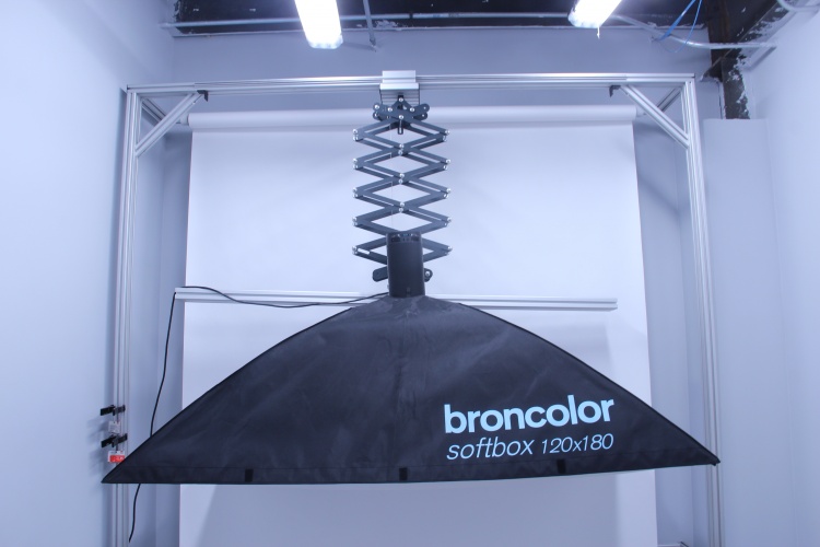
The most important design function was bracing the photography light that shines into the “soft-box”. For it to function correctly, the soft-box has to surround the product being photographed. At the same time, the photo booth had to fit in our photo studio and be mobile. Therefore to add additional area that the soft-box could cover, a linear slide was added to provide extra cover area.
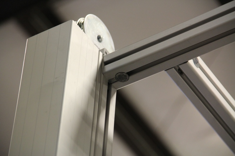
The project was initially designed with a traditional photography drop-down system that helps hold a soft-box in place. The drop-down system was an adjustable pantograph. The pantograph required high spring force to keep the it and the light in place. The combined weight of both pieces and the high spring force was a major issue. The pantograph flexed outward, causing integrity issues and it was almost impossible to raise and lower. In addition, a piece of 80×40 aluminum profile was used to balance the front-heavy weight from the light, forcing the pantograph spring force to be set at an even higher rate.
This system functioned, but we knew it could be done better. We termed this the “beta stage” for our photo booth.
After using the beta photo booth for a couple of months, we thought of ways to improve its functionality. Initially, our design requirements did not call for mobility or quick disassembly. These two key features were added to our list of improvements, along with other new requirements, after the trial period, especially seeing how difficult it was to move this large piece into the production area.
We decided to use what we know best – extruded aluminum. This would enable the photo booth to be mobile, taken apart for transport and provide low resistance adjustment for raising and lowering the lighting. Ultimately, the modifications have provided us the flexibility for product imagery for a vast array of project sizes.
One major thing that needed changed was the drop-down system. It didn’t work the way we wanted and there were much better ways to design the drop-down functionality.
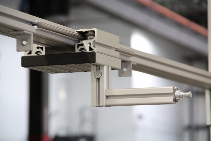
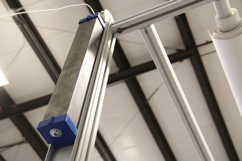
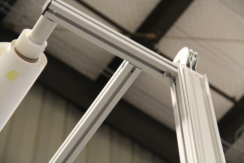
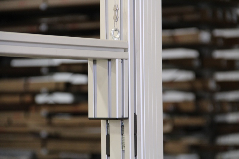
The drop-down function of the design was changed to a counter-weight system; made with conduit profiles, cabling, and roller bearing units for smooth and stable transitions. The lighting and its connecting frame weighs 43 lbs. The counter-weight configuration allowed for an easy 1 lbs of force to raise or lower the independent lighting frame (light/soft-box included). Previously, the pull/push force was nearly 150 lbs. The benefits didn’t stop there. The travel distance increased as well. Now the lighting has a respectable 1200mm (47″) travel distance on the Y plane.
Due to the size and weight of the photo booth, mobility and disassembly were factored into the design. To add mobility, caster wheels were added to the bottom of the frame itself. The unit now moves with ease. For disassembly the unit was built into two pieces. The top consists of the lighting frame and frame structure. The bottom consists of the feet and framing structure. The pieces are fastened together with eight automatic-butt fasteners. The unit takes roughly two minutes to break down into pieces for quick transport.
Below are some of the T-slot profiles and components used to create this project.


Final Thoughts
Not only do we now have a functioning photo booth for product photography, we created a system that can be used for photographers across the world. Photography equipment is expensive, paired with large amounts of travel from studio to studio, this creation provides photographers flexibility to travel with equipment, while being able to setup quickly.